Electro-slag Welding 101

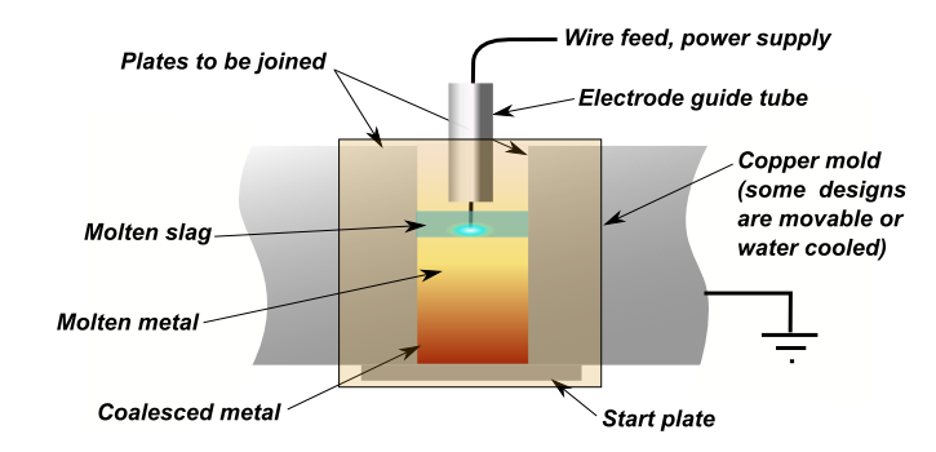
In the late 1930’s, electro-slag welding (ESW) process was first created in the United States then patented by Robert Hopkins in 1940. The E.O. Paton Institute in the Ukraine developed ESW further with other metals and materials. ESW is a process that produces coalescence of metals with molten slag that melts the filler metal and the surface of the workpieces. Slag is formed when iron or iron pellets (either limestone or dolomite) are melted together in a blast furnace.  The weld pool is shielded by this slag which moves along the full cross section of the joints as welding progresses. The process is initiated by an arc that heats up the slag. The arc is then extinguished by the conductive slag which is kept molten by its resistance to electric current passing between the electrode and the workpieces. ESW is the primary method used for cast weld assemblies of heavy sections due to one of its key characteristics of a high deposition rate. ESW is often used in structural box columns and wide flanges.

Much like submerged arc welding (SAW), ESW is also used for welding in the vertical position. Both utilize bare electrode wires fed continuously into a molten slag pool contained between water-cooled dams. The arc is then extinguished by pre-deposited flux. The molten pool of weld metal and base metal that is maintained by the heat generated from the resistance from the flux to the passage of current from the electrode to the base metal creates a molten resistor that is heated approximately to 3,500°F. If heat escapes the molten flux and weld pools too rapidly, the cross section of the weld could result in barrel shape, or incomplete fusion at the weld corners. The deposition weight of the weld, minimal joint prep involved, and vertical position needed all contributing to limiting the process to large weld projects or repairs normally using carbon or low alloy steel. The deposition rate is the relationship of the weight of the weld metal deposited to the weight of the electrode (or wire) consumed in making a weld. Weight of metal divided by weight of electrode used leaves you with the deposition efficiency expressed in pounds per hour. The higher the deposition rate, the lesser the amount of metal is wasted by not becoming part of the deposited weld metal. In short, ESW prevents a large percentage of welding consumables from being lost to slag, patter, and fume, giving fabricators the leading determinants of the cost of the effectiveness of a consumable. This can be very sought after depending on the end result asked to be achieved.

Like all fabricating procedures, depending on the final result of the part needed, there are disadvantages and advantages to each chosen. Unlike SAW, or other similar arc welding processes, no angular distortion or residual stresses occur with ESW because the weld is symmetrical in respect to its axis. Due to its vertical position, it produces a high welding speed creating a healthy amount of stress distributed across the weld. As mentioned before, its important the molten resistor is heated to approximately 3,500°F, as any higher could result in the weld quality being poor, allowing toughness from the grains in the fusion/heat-affected zone. ESW is also restricted to a vertical position with welding, which can be great to link thick metals together, but not advantageous for less thick parts.

Many factors have to be considered when selecting a welding process for a particular purpose or functionality. The types of welding needed to be performed, the types of steel, and the size and quality are only a few of topmost considered factors to be evaluated prior to any fabricating process. Electro-slag welding is no longer considered to be THE one option to link thick steel plates. With modern technological advances in ESW, its role has expanded beyond flanges to the construction sites of major high-ride bridges and buildings. ESW has been proving time and time again how cost-effective it can be for the reliable creation of large welds involving bridges and buildings.

Tolerance – Why It’s Important

Tolerance is a word that is tossed around a lot in the welding world and it stands as the most analyzed element for evaluating manufacturing quality. Tolerances are critical to the manufacturing process as they determine how well a part will fit in the final product and how stable that product will be. A tolerance can be used in reference to mechanical fit, proper alignment of holes for assembly (“fit up”), and deviations from straightness or accuracy of assembly. Tolerance is one of the most important considerations for those deciding on which metal fabricator to choose.

Tight tolerances are not universally achievable at any given shop. The newer technologies such as cutting, machining, and welding make this an even harder process leaving more opportunity for error. Workpiece parts go through several processes in any given manufacturing cycle. Multiple people touching a part, the quality of the assembly, and the tolerance capabilities among outsourced manufacturers are key reasons why outsourcing a part or finishing the assembly with multiple vendors can lead to further tolerance issues. It is best to have as many processes as possible consolidated in one space where everyone has a general understanding of how each service interacts in the making of the parts. In-house manufacturing will always be more favorable to achieve tighter tolerances since the manufacturing process is evaluated and refined all in the same spot. In-house engineering on top of in-house manufacturing can ensure an even tighter tolerance as there will be more understanding of how each machine or person interacts with a part. Geometric dimensioning and tolerancing (GD&T) is an established method for communicating engineering tolerances. This communication enables engineering tolerances and allows engineers and anyone else working with the part to anticipate tolerance constraints before the manufacturing production starts. GD&T is still up and coming in the manufacturing world and today is only found among a few metal fabricators around the U.S. GD&T is a powerful language and tool that could greatly benefit the manufacturing side of the processes.

One of the more important aspects of tolerancing is understanding that when tolerances are so tight, they do nothing but drive up the cost of production and slow down how fast manufacturing gets their processes done. As noted above, tolerances are used to ensure the fit and utility of the part. If the proper functionality and fit can be achieved with a looser tolerance, that option should always be taken even if it’s possible to achieve tolerance that is tighter. Why? Ensuring as tight of a tolerance as possible on a part that doesn’t deem that requirement is not worth the loss of productivity and increased cost that will need to be factored into the end result. Sometimes, less really is more. It’s helpful to consult with your manufacturer on their experience with similar work since they have probably seen similar tolerances and can make the best recommendations.

Tolerances can always vary depending on the type of equipment available on the floor at a given time. For precision cutting, machines have little room for error, leaving the metal fabricator almost entirely dependent on the technology available. It’s important to note which equipment will be available to whomever is working your project. This will ensure that the quoted tolerances can be met on a consistent time basis. Sometimes having a certified weld inspector (CWI) can be helpful to ensure proper tolerances are being hit.

Some places will take precautions to the next level by having a risk management team. A risk management team will not only mitigate the risks associated with poor tolerances but will reduce the quantity of faulty parts within its production style. Having a risk management team or something similar within the facility will give the fabricators the ability to reflect their objective data on their work done and assess how to make further improvements. The tighter the tolerance, the more time risk management has to take guaranteeing quality. When considering tolerance, the fewer people and machines involved the better. Luckily, the tight quality tolerances you’re looking for can be found here at MFI because everything we produce is in-house including tolerances for the final product. Time and money will be saved by eliminating several unnecessary layers of outsourced contractors/manufacturers by manufacturing in-house. At MFI we can assure you quality workmanship will be done.

Understanding Bend Tests & Radius

Welding procedures require bend tests for many parts such as tubes or pipes. It’s important to know the properties of the part to be worked on. The inside bend radius (sometimes called the intrados), the outside bend radius (extrados), and the centerline radius (or neutral line) where neither compression nor stretching occurs are all critical variables when bend testing.

The distance between bends (DBB) is the distance between two tangent points where a straight section begins to curve and the bend finishes. Similar to press brake forming, tubes and other parts experience a springback after being bent, which can produce radial growth in the tube. Depending on the metal of course, outcomes will vary. For example, stainless steel will have more radial growth post-bend than copper. The quality of the metal, size, and consistency of weld seam are all integral parts of the finished bend. If two edges of a joint aren’t aligned correctly, or the weld bead (deposited melted filler metal) isn’t the right size, it could end up affecting the shape of the tube negatively and the “perfect bend” won’t be achieved. “Elongation” is the term coined for when the outside radius stretches causing wall thinning. This causes the outside of the surface of the bend to cave in, resulting in an oval type shape much distorted from the original desired round shape. Most tubes are bent by ram-type bending, roll bending, compression bending, or rotary draw bending.

Ram-type bending uses a hydraulically driven ram that forces a tube against rollers or pivot blocks and can achieve three to four times the original diameter of the workpiece. These types of benders can be found in any muffler shop. This particular method is popular in square tubing applications. It is the least expensive way to bend tubes or pipes; however, it is not as controllable as some of the other methods. If one is in need of certain aesthetics or cosmetics to the workpiece, or need tight bending tolerances, the ram-type method may not be the most suitable.

Roll bending is generally used for large workpieces in construction. The material is formed by applying force from two to four rollers within a CNC machine. There is a narrow gap between the two middle rolls through which the metal sheet is fed. In this setting, a metal sheet panel would pass through the machine without being bent. After the CNC machine is set to roll bending, the middle rolls down in relation to the two side rolls to create the bend. The deeper these rolls are set, the smaller the bending radius. The smallest bending radius is equal to the upper roll diameter. The metal is not cut or removed. Roll bending is generally used when a metal sheet is to be given a large smooth radius, or to produce spirals.


Compression bending uses a roller as well or a compression die to bend the workpiece but instead compresses it around a stationary bend die. It clamps the workpiece from behind and compresses the tube against the stationary bend die. This is a good method for those creating symmetrical workpieces. Identical bends can be achieved with this use in one go with the machine creating two bends on each side. This method is mostly used to produce household items and commercial products. An example of compression bending that can be seen in the daily world would be a towel bar with two identical bends on each side hanging on the wall of a bathroom.

Rotary draw bending is ideal for tube bending involving tight radii. This method gives the utmost control regarding wall thinning and risks of ovality that ram-type bending may fall victim to. Rotary draw bending supports the metal being bent used a mandrel inside the tube while utilizing precision tooling on the outside. A rotary draw bend entails a pressure die holding the straight section of the tube, a clamp die rotating the workpiece around a curved rounded bend die, a mandrel with a series of balls on the tail end to support the interior of the tube around the bend, and a wiper die that wipes the workpieces tangent point of the inside radius to prevent against any wrinkles that could potentially be formed in the process. The pressure die also supports the outside radius of the tube during a bend. More common today, hydraulics are being used by pushing against the pressure die to minimize wall thinning further. Each element involved in rotary draw bending allows for total control of the inner and outer diameter throughout bending. It’s important to practice attentiveness with what metals and tools you’re working with when rotary bending. It’s important to have a combination of hard and soft materials. When using a hard work piece, a soft mandrel is optimum. If mandrel is too hard it could get stuck inside of the tube. Respectfully, a soft workpiece would in turn require a harder mandrel.

There is always a level unpredictability involved with any trade; however, with the advancements of modern technology, bending will only become more precise every time. Whether working with pipes or tubes, whichever method of bending utilized is always relative to the quality of the material, machines, tools, and lubrications involved. Also, knowing the proper bends is just as important as the quality of material being used. Due to different levels of spring back from different metals, it’s crucial to know what’s best for the desired outcome. Here at MFI, we utilize the ideal bends for our end user’s desired project requirements and can assure that our expert fabricators will produce the highest quality products.

CNC Machining 101: Welding vs. Riveting

When designing something that requires two pieces of metal to be brought together, it’s important to consider whether they will be welded or riveted. Welded joints and riveted joints are two commonly used permanent joining processes. Both welding and riveting have strengths and drawbacks that will create a part that lasts a long while depending on the project at hand.


Riveting


CNC riveting is a mechanical process that permanently fastens geometric shapes ranging from simple to complex. Rivets are cylindrical metal shafted tails or mandrels that have dome-shaped heads. These types of fasteners create a watertight join when connected through the glowing hot drilled holes. When the metal cools, the rivet contracts, and the two parts become one. Riveted structures are generally heavier in weight. Blind rivets are used in a variety of metals including aluminum steel, stainless steel, and copper. A hole is drilled and then the rivet is set inside of the hole. The machine or fabricator then pulls the mandrel of the rivet to reach the designated peak force until it eventually snaps off. This leaves a “blind” or flush-looking properly installed rivet. One of the biggest advantages to riveting is that there is no way to under-torque rivets. A rivet will install perfectly every time as long as the correct diameter and grip range are chosen.

Riveting is one of the oldest technologies, and was used for ships, structures, and vessels before World War II. CNC riveting can be used for a variety of operations such as for aircrafts, structural beams, small electronics, RVs, and submersibles. Many CNC riveting machines are made for manufacturing lines, making turn-around time faster with a higher degree of automation.

Welding

Welding is the more familiar method of fabrication widely recognized in the industry to join metal materials. Welding also fuses two pieces together, either manually or with the help of a CNC machine. Instead of heating up the individual parts of metal that are being formed together, welding uses an external high heat source that melts the pieces to conjoin them. Welded joints always provide very high efficiency compared to a riveted joint. When thinking about aesthetics, welding will always give a smooth, visually-appealing structure while also having comparative strength to a rivet. Welded structures tend to be light in weight compared to riveted structure due to the fact that in welding, gussets — the connecting components — are not being used. Alterations and additions can easily be made within the welded structure, whereas once a rivet is in place, there is no longer room for altering. Some disadvantages to welding include uneven heating and cooling involved in the process. This factor can inhibit additional stresses to the metal. The inspection for defects tends to take longer for welding structures due to the heating and cooling process, which will also result in more manual labor for the fabricator.


Both Great: Depends on Project & Finished Appearance Desired

 Many riveting structures were replaced by welding after World War II because welding was less time consuming. Riveting requires holes being made, proper assembly with the rivets, pressure, and correct grip diameters before being assembled, whereas welding only requires assembly without much preparation. The loss of metal due to the hole in the rivet structure ultimately makes it a weaker bind. Welding does not consist of any metal loss like so, leaving it with a rather stronger connection. Welding, whether using CNC machines or fabricating manual labor, tends to be a quicker and generally cheaper process due to fewer steps and parts needed. Drilling holes, inserting the rivets, heating the protruding end — all these steps take up a substantial amount of time in comparison to a weld. However, for very thin sheet metal, welding might not be sufficient as its possible to burn through. Rivet holes tend to stretch and have a more calculated clearance when welding may not be the best alternative. As with most things in engineering, not everything is a ‘one size fits all’ — and with riveting and welding that phrase most definitely holds true. Here at MFI we pledge to utilize the best method for conjoining metals based on the end user’s desired requirements.


CNC Machining 101: Milling and Turning

cnc machine
CNC (Computer Numerical Control) machining is a subtractive manufacturing technology where parts are created by removing material from a solid block, called the blank or workpiece, using a variety of methods. The removal of material has significant implications on the benefits, limitations, and design restrictions of CNC. Since CNC machining is a digital manufacturing technology, it produces high accuracy. The high level of automations required makes CNC machining competitive in price for custom parts and medium volume projects.

The most common metals used for basic CNC machining are aluminum, steel, brass, and plastics. However, almost every material can be CNC machined. Firstly, the engineer must create the CAD file for which the metal will be shaped. CAD is Computer-Aided Design software for engineers or architects to create two-dimensional or three-dimensional models. Once the design is complete, the machinist turns the CAD file into a CNC program and sets the machine. The CNC machine then executes the CAD file design completely automated, removing the materials necessary to create the end product.

When CNC milling, the workpiece is held stationary directly on the machine bed. Milling incorporates the technical aspects of both drilling and cutting processes, and CNC milling uses a rotating cylindrical cutting tool just like in drilling. Precise positioning and alignment are key for manufacturing accurate parts and special metrology tools (touch probes) are often used for this purpose. Material is removed from workpiece using cutting tools or drills that rotate at high speed. The tools are attached to a spindle, which moves along a linear axis. The cutter and workpiece move along several axes with tight tolerances. If the model has features that cannot be reached by the cutting tool in a single step, then the part needs to be flipped and the prior steps then repeated. After milling, the part is then sent off to be deburred. Deburring is a manual process of removing the small defects on sharp edges due to material deformities from the CNC machining.

CNC turning is when the part is mounted on a rotating chuck and materials are removed using stationary cutting tools. The metal part to be worked on is then placed along the center axis. Like milling, a CAD model and blank material are loaded in the CNC machine. The part starts to rotate at high speeds and a stationary cutting tool traces its profile, gradually removing material until the designed CAD model is created. CNC turning systems (lathes) are normally used to create parts with cylindrical profiles. Non-cylindrical profiled parts can be manufactured using a multi-axis CNC turning center, which are furnished with milling tools. Milling and turning are very similar processes but different in how the part is executed.

Drills and other cutting tools are used often along the center axis to create different geometries when milling and turning. The most commonly used milling tools in CNC include the flat head, bull head, ball head, drills, slot cutter, and fact cutters. Drills are a quick way to create holes. Flat heads, bull heads, and ball heads are used to create the grooves, cavities, and walls. The difference in each of the head’s geometry allows different, detailed features. A slot cutter’s diameter shaft is smaller than the diameter of their cutting edge to cut T-slots and undercuts from sides of vertical walls. Face milling cutters are used to remove material from large flat surfaces. With a larger diameter, they require fewer passes to machine large areas, producing clean flat surfaces.

CNC machining not only increases productivity, but it saves time and money in the process. It can produce parts with tight tolerances, making it ideal for high end applications. CNC machining is great for both one-off jobs and low-to-medium volume production, especially for metal prototypes as it is the most price-competitive option. At Merchants, depending on the project requested, our talented fabricators utilize CNC machining milling and turning to make a variety of parts.


Sheet Metal Finishes for Aesthetics and Longevity

sheet metal finising
You may think sheet metal finishes sole purpose is for aesthetic. Why else would it have that beautiful matte finish that’s so symmetrical and perfect? You may not be aware that certain finishes aren’t just for eye catching designs — they are also for protecting the product depending on its use. For example, sometimes a special chemical coating is used to change the surface of the metal to make it more adaptable for its intended use. The process of applying a specialized finish to sheet metal is not new. In fact, sheet metal finishes are everywhere. Generations of manufacturers utilize different finishing techniques to enhance their corrosion resistance, scratch resistance, and overall functionality. We’ve outlined some neat finishes and coatings to look out for when designing the functionality and appearance of a fabricating project.

Chemical conversion coatings have specialized purposes tailored to particular types of sheet metals. The most common types are anodized, chromate, zinc, and passivate. These coatings help limit the corrosion that would normally happen when steel, stainless steel, or aluminum are exposed to elements. For instance, if you want to improve electrical properties of stainless or aluminum parts, chromate would be the chemical treatment used. To improve corrosion resistance yet also add some color for aesthetics, you’d want to anodize.

Powder coatings are one the most common sheet metal finishes. First, a small electrical current is run through the metal. Then, a powered polymer pigment is sprayed on with a nozzle, forming a bond with the metal through electrostatic attraction. Powder coatings top paint for aesthetic reasons due to quick drying and a more uniform solid finish, and they come in several different colors. Powder coatings are decorative and protective from corrosion and heavy usage.

Silk screening is strictly for aesthetics, and the process is the same way people add logos to T-shirts. A fine mesh screen allows ink to transfer through, but only in designated areas that you choose. It is recommended that you choose a smooth powder coat finish before silk screening so the graphics produced have a greater effect.

Anodizing is an electrochemical process that increases the corrosion resistance of a metal part by forming a layer of oxide on its surface. Submersing aluminum in an acid electrolyte bath while passing an electrical current through it forms an aluminum oxide coating right from the aluminum itself. The results are a hard, durable coating that’s resistant to corrosion and never peels or chips.

Metal plating is one of the most common metal finishes. It’s when you cover the surface with a thin film of another metal. These metals usually consist of nickel, silver, gold, etc. to make it corrosion resistant in certain environmental conditions. Metal plating is typically used to decorate certain projects, like jewelry, instruments, electronics, and furniture.

Brushed metal and metal polishing finishes are similar, but not entirely the same. Brushed metal finish is ideal for removing imperfections from the surface using special abrasive brushes and is generally used to achieve a granular/scratched texture. Metal polishing can be seen as removing imperfections as well, but on a smaller scale. Tending mostly to stainless steel, copper, and aluminum metals, polishing and smoothing entire objects is generally used to give a really glossy, polished finish to damaged or neglected metals.

Dual action or directional finishing is utilized after the course of handling the material after it gets nicked or scratched.  Removing these defects involves a mild grinding of the surface in a non-directional or random pattern.  In effect, it adds small scratches randomly across the entire surface.  Direction finishing is the “graining” or scratching of the surface in a particular uniform direction.  For example, a widely recognizable use of this type of directional finishing is on stainless steel kitchen appliances.  The appearance can vary given the grit or grain size of the abrasive use to produce the finish.

There are many different types of metal finishes to which metals are subjected. Originating from engineering, a metal component passes through the sheet metal bending, punching, threading, and other processes before arriving to the final phase of work: the metal surface finishing process. A variety of factors should be taken into consideration when choosing a metal finishing process. If your operation requires a quick turnaround time, you’ll need to choose a process that is compatible with tight deadlines. Another factor is the hardness of the metal or other material you’re working with. A process that is overly abrasive could damage the metal, while one that is too gentle may not achieve the preferred result. Here at Merchants, the option to choose any of these finishes for your desired project is attainable. Our master fabricators have a solid reputation for superior quality parts and finishes along with excellent turnaround time and delivery.